How it’s made
JPen (John Patrick Engineering)
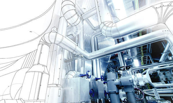
Metal Fabrication Design
The in-house design team features a comprehensive, integrated skillset. The draught persons are trained and well versed in the use of CAD software to either create plans from concept or integrate existing customer drawings into multi-component fabrications.
In addition to our regular service operations, we are frequently presented with projects that require articulated solutions, this can involve the liaison with our design team with civil engineers and architects. Communication vital at this stage to establish the working draught ready for deployment to the workshop.
The backbone software used at JPEN is AutoCAD LT, the module components licensed and installed with this software allow for a considerable number of mainstream file types to be loaded and edited.
Hot and Cold Forging
This is a manufacturing process to shape metal using direct forces to compress and re-shape a part, it is recognised as one of the oldest recorded metal working processes. Forging is an art historically performed by a metalsmith (blacksmith) using anvil and hammer tools. With the advance of power and technology, much greater works of metal can be created in significantly less time, none the less the underlying principles of physics remain the same. Most industrial forging is completed with the use of compressed air or electric powered hammers in addition to metal presses.
There are advantages and disadvantages to forging metal. When the metal is reshaped through the forging process, deformation is caused to the internal grain matrix so that it ends up following the shape of the part. Essentially the result from this is that the texture becomes more uniform throughout the part thus improving the strength characteristics. Scrap wastage is minimised with the process; however, this has to be offset against the requirements of hot forging for iron and steel.
Cold Forging
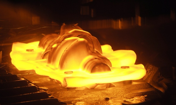
Hot Forging
With hot forged parts, secondary machining operations become increasingly difficult to work with due to
Each type of metal has different properties that affect hot forging temperatures, aluminium can be forge at almost half that of steel, the tolerance range before cracking or alternatively folding is much less than the former. Aluminium alloy forged parts are typically used in the aerospace and automotive industries as they provide the tensile strength of medium strong steel alloys without the considerable weight penalty.
At this time JPen employs some cold forging operations including rolling and forming which are intrinsically cost effective to customers requiring
Cutting
Arguably this is more of a parent classification for milling, turning, threading, grinding and filing
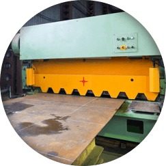
Guillotine
Hydraulic guillotining is sometimes referred to as a power or squaring shear. A ram clamps the material followed by a moving blade coming down across a fixed blade to shear metal. In the case of larger surfaces, the blade may be rocked (angled) on order to shear the material in a progressive manner, using an angle in this way greatly decreases the amount of force required to perform the cut.
Plasma
A highly favoured process whereby electrically conductive materials are shaped and cut by the use of an accelerated jet of hot plasma. Regular materials encompass stainless steel, aluminium, brass and copper. Using CNC programs, articulated shapes can be cut from metals using an electrical arc plasma comprised of ionized gas. The electrical current travelling through the plasma generates sufficient heat to melt through the workpiece. Flatbed plasma cutters can cut steel up to 150mm in thickness. Plasma cutting allows for the production of more decorative metalwork such as signage, garden panelling and wall art in addition to more functional fabrication uses.
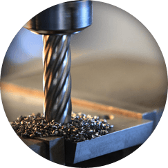
Milling
The milling process is the complex shaping of metal by the removal of material to create a final shape. These machines feature a cutter head similar to a drill; these can move in various axis planes depending on the grade of machine, the most commonly used configuration enables 2 axis of movement. Regular milling techniques include, planning, drilling, threading, routing and slot cutting.
During the milling process the machine head and the target material are kept cool by means of a high temperature coolant. The density of the material denotes the speed of the milling tools and the subsequent amount of material that can be removed by a pass of the tool head. The complexity of the parts being milled in conjunction with the type of material used very much dictate the time and subsequent cost of output. There are stiff health and safety measures in place for working with these types of machines to protect operators, even for CNC controlled devices.
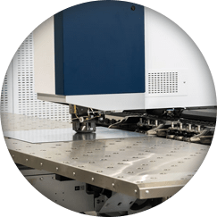
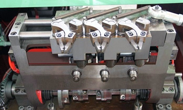
Punching
A popular metal forming process uses a force tool to punch through a work piece to effectively create a hole via shearing. Punching is generally applicable to a wide variety of sheet form metals, the punch passed through the surface into a die; the scrap piece often referred to as a slug is deposited into the die itself. Generally the metal slugs can collected and recycled.
Due to the nature of the materials and the powerful forces involved at the point of contact, the punching tools have to be made of either hardened steel of more often tungsten carbide. It is necessary for the die to be located in close proximity on the base side of the sheet material to act as a means of support during the shearing process. The clearance between the die and the sheet material must be greater than the thickness of the material itself to prevent the punch from sticking into the die.
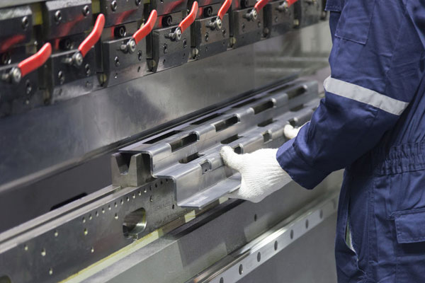
Forming
Metal forming is a process whereby metal objects and parts are created through mechanical deformation. The mass of the original material remains unchanged, only the dimensions and shape are affected. The underlying principle within material science is that of plastic deformation, essentially the material (in this case metal) is permanently deformed from its original state, it is therefore said to have no memory properties. A popular machine in fabrication is known as a press brake, these machines are useful for producing variable angled bends in parts using a die and deformation tool.
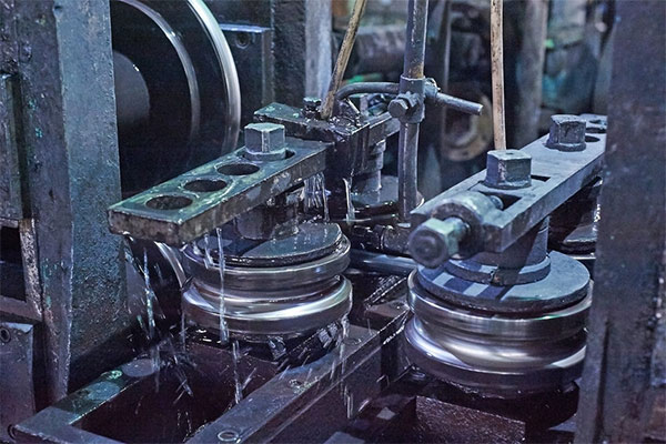
Rolling
A process where uniform metal pieces are passed through one or more pairs of rolls to reduce the thickness and produce a uniformity in the thickness of the overall product. Cold rolling is when the metal is rolled under its crystallisation temperature.
It’s important to differentiate between two distinct sub- classes of rolling, these are roll forming and roll bending. The former, roll forming (also spelt rollforming) works on the concept of continuous bending of a long section of sheet metal to create a desired cross section. The material is passed through a sets of rollers mounted on opposing stands, each set of rollers performs defined increments of the desired bend until the desired profile is achieved.
Roll bending can be used on sheet metal and metal bars to form the material into a circular arc. A minimum of 3 rollers are required to perform the process of plastic and elastic deformation. The rollers move the bar or sheet, pressure is increased on each pass to produce the required arc radius. The ductility of the material is relative to the elastic potential, therefore aluminium is more apt to being fashioned into an arc than steel bars.
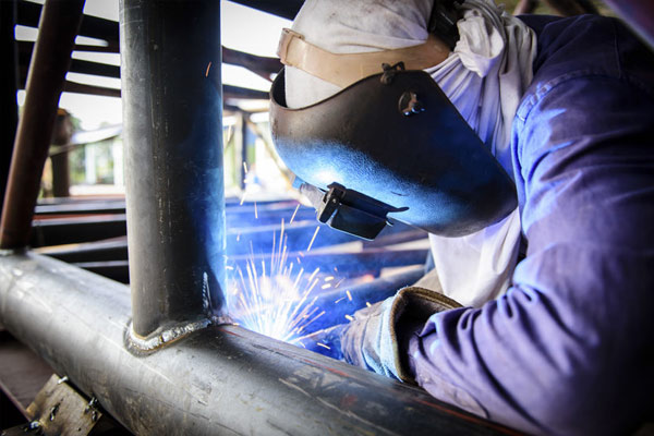
MIG Welding
Gas metal arc welding often referred to as metal inert gas (MIG) welding, is a process when an electrical arc forms between a wire electrode and a workpiece metal. The metal workpieces are heated causing them to melt and join, a shielding gas feeds through the welding tool, the gas protects the process from contaminants contained in the air. The technique is effective on heavy and light steels as well as aluminium with the use of either semi-inert (CO2) or inert gases. A constant voltage supply maintains the arc length in order to keep the heat input and current constant. Shorter arc lengths cause the wire electrode to melt more quickly, generally direct current systems are used with the electrode being positively charged. The composition of the utilised electrode is dependent on the properties of the composition of the metal being welded. The material type of the electrode strongly influences the mechanical properties of the weld which in turn dictates the weld quality. Ultimately the finished weld should have mimetic mechanical qualities of the base material with the limitation of both contaminants and porosity. All commercially available electrodes contain deoxidising metals to assist in the prevention of oxygen porosity.
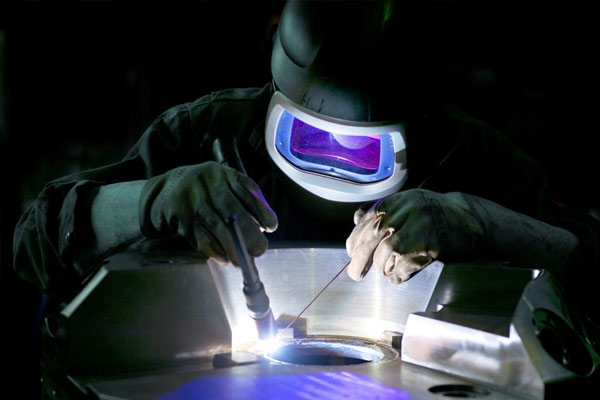
TIG Welding
Gas tungsten arc welding is also referred to as tungsten inert gas welding. This procedure relies on the use of a non-consumable tungsten electrode to produce the weld. An inert gas, either argon or helium, is used as a shielding gas to prevent oxidation and atmospheric particulate contamination. Some welds make use of a filler metal, although the technique can be used to create autogenous welds (the material being welded is melted itself to form the join with the other metal surface). The use of a constant current power supply feeds electrical energy which is conducted over an arc via a column of highly ionized gas and metal vapours more commonly known as a plasma. The technique is suited to thinner sections of stainless steel, aluminium and copper. Unlike MIG welding, the TIG process provides the welder with increased articulation allowing for stronger, higher quality welds. TIG welding is considerably harder to master and often a slower process than MIG welding.